
Wednesday
End of the Year
It's 10:48 on Wednesday, May 30, 2012. In a few hours school will be out for the year, and E-Zine will be over. Never the less, our magazine is finished! Although Jonas, Miles, and I are amateurs, we're glad that it came out as good as it did. Read it here on MagCloud, or download it for free.
Thursday
Cost Efficient Tools
 |
| A picture of the Dremel 300 |
Second to the Dremel would be a scroll saw, simply because cutting thicker wood is extremely slow with the friction-based cutting bits that come with the Dremel. Perpendicular cuts are something difficult to do with a Dremel, but quite easy with a proper saw. Although less powerful, scroll saws are generally much cheaper than a band saw and can make more accurate cuts.
Although at first a drill press appears silly if one already has a hand drill, the precision in depth that one is capable of with a drill press is unobtainable with a hand drill. There are a few fairly cheap drill presses one can find, a large stand alone one is rarely necessary on a personal scale.
Wednesday
Déjà Vu
You've heard of CAD programs, right? Computer Aided Design... I just recently found out that the first of its type was also the precursor of the GUI.
In fact, I would say it's almost the same program.
That doesn't mean that SolidWorks plagiarized Sketchpad, though, I am sure, it was very heavily influenced, but I'm just surprised either that programming geniuses of today are not able to come up with a substantial improvement in the user interface ( in which case Sketchpad would be left behind ) or that such inventions could be made in one huge step in 1963 that there's nothing left to do. I guess I'll never know which.
A few days ago I came across a Wikipedia article on Sketchpad. Written by Ivan Sutherland in 1963 as part of a PhD thesis, it was a program that allowed the user to use a light pen to interact with a computer in order to draw lines and circles. Even more ingenuously, you could join together these "instances" of figures to create a bounded two-dimensional shape and then strictly define their positions and dimensions. In other words, for that time, it was amazing.
 |
| Photo from resumbrae.com |
I'm almost tempted to omit that phrase, "for that time." See, last semester I took a class titled SciTech, for part of which we used the drafting program SolidWorks. Not only is the application the best of its type I have ever used, but as I was reading Sutherland's thesis, Sketchpad seemed curiously similar to it, despite the fact that it was not 3D.
In fact, I would say it's almost the same program.
That doesn't mean that SolidWorks plagiarized Sketchpad, though, I am sure, it was very heavily influenced, but I'm just surprised either that programming geniuses of today are not able to come up with a substantial improvement in the user interface ( in which case Sketchpad would be left behind ) or that such inventions could be made in one huge step in 1963 that there's nothing left to do. I guess I'll never know which.
Tuesday
Now, the Software?
Over spring break I built another axis of my 3D printer. That's two dimensions of movement... getting about halfway there. Anyway, soon I shall need software to control it.
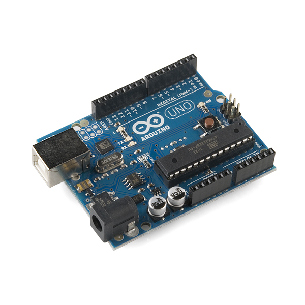
The problem there is that it will all have to be custom-written. There is nothing that I know of that will do what I want: control three stepper motors with an Arduino Uno alone. Therefore, I'm coding...
So far, I can control a single motor. However, I'm having to implement threads in order to run multiple motors at different speeds; it should work, though.
A more pressing matter is sending the g-code to the Arduino; that is, the ability for a computer to read a file and communicate building instructions to the 3D printer. I don't think it will be very hard:
This is a g-code interpreter I made in the last few minutes. It reads a “.gcode” file and stores the individual moves the printer has to make, then outputs a point at each vertex of movement. As yet, it can rotate in 3D; I still have to work on a GUI for a printing application. In that application, then, I can communicate with said Arduino! Serial... in Java!
Sounds like fun to me.
The problem there is that it will all have to be custom-written. There is nothing that I know of that will do what I want: control three stepper motors with an Arduino Uno alone. Therefore, I'm coding...
So far, I can control a single motor. However, I'm having to implement threads in order to run multiple motors at different speeds; it should work, though.
A more pressing matter is sending the g-code to the Arduino; that is, the ability for a computer to read a file and communicate building instructions to the 3D printer. I don't think it will be very hard:
 |
Photo by Daniel |
This is a g-code interpreter I made in the last few minutes. It reads a “.gcode” file and stores the individual moves the printer has to make, then outputs a point at each vertex of movement. As yet, it can rotate in 3D; I still have to work on a GUI for a printing application. In that application, then, I can communicate with said Arduino! Serial... in Java!
Sounds like fun to me.
Sunday
More problems, more solutions
The method I am using to make my daft punk helmet is quite a large investment, as it relies on making a mold and then making up the loss of money by mass producing the product. To do this, I am making a mock-up of the helmet using a cardboard frame and expanding foam. This will have the same outer shape as the helmet. Afterward, I will make a mold from this using silicone from smooth-on. Using a method of lining the inside of the called slushcasting, I will make replicas from the mold. Now, i have almost finished a mock-up, but I found that the dimensions were actually much smaller than I needed. I have decided that it would be easier to remake the entire mold with a larger foam base than it would be to simply layer on Bondo to get it to the appropriate size. Fortunately, this should easier the second time around due to the learning curve behind working with foam.
Something positive, though, is that I got the electronics to work, and it's quite pretty.
Something positive, though, is that I got the electronics to work, and it's quite pretty.
 |
| A typical example of slush casting, from Tyr on TheReplicaPropForum |
Monday
Arduino coding
The largest difference between coding on an Arduino and coding on a computer is the lack of processing power present on an Arduino. Thus, I have been looking through the use of bitshifts and other such low-processing power commands. I have been looking at coding for the ears on the previously mentioned Guy Manuel helmet, since this is fairly simple to code for it is a good opportunity to try out syntax that I don't normally use. For example, before I used a digital "light source" and an array of points (nodes) to calculate the amount of theoretical light that the nodesd would receive, so that I could simulate a single mobile light source moving throughout a one dimensional string of LEDs. (I apologize if that sentence is a bit unclear, but the encompassing idea behind it is that the algorithm I used was overly complex.) This was extremely inefficient. Thus, I instead used a byte and bitshifts to function as a simple one-dimensional array. This is very easy on a processor to do, the only problem was reading in the byte as a bunch of bits, which is strangely difficult with the limited library that is given on the Arduino website. Thus, I need to teach myself proper C++ and use that rather than the default Arduino language, which is merely a modified version of C.
Again I apologize if that came off a bit convoluted, I tend to ramble.
Again I apologize if that came off a bit convoluted, I tend to ramble.
Sunday
Circuit Diagrams: A brief look at something I knew nothing about.
I know that it is very strange to write about something that is really new to you but i think that it is one of the best ways to get it into your head. Before i started working on this magazine project, or more importantly before i was placed in my group, I had a very rudimentary idea of what a circuit diagram was, that being exactly what the name suggests. But after being placed in my group and hearing the term come up quite often, I decided i should probably figure out more about its purpose.
A circuit diagram is exactly what its name suggest. a diagram of a circuit. They are used to graphically show how all the different parts in a circuit are to connect. There is a very simple one (pictorial) that just shows pictures of the actual things that are being connected, this one takes up more space but is easier to comprehend. The second one (schematic) utilizes symbols, that have been agreed upon in some fashion and are used worldwide, to diagram the circuit fully. This being said, the symbolic one is a lot more daunting at first. Circuit diagrams do not show location though, they just show the connections an the easiest way to represent them graphically.
There is plenty more stuff that you can learn about circuit diagrams. I know i didn't include that much about circuit diagrams. I just included what i thought was important.
Miles
 |
| picture was obtained from here |
There is plenty more stuff that you can learn about circuit diagrams. I know i didn't include that much about circuit diagrams. I just included what i thought was important.
Miles
Subscribe to:
Posts (Atom)